Coordinate System in GIS: A Guide to Accurate Mapping
Coordinate Systems
The location of a pixel in a file or on a displayed or printed image is expressed using a coordinate system. In two-dimensional coordinate systems, locations are organized in a grid of columns and rows. Each location on the grid is expressed as a pair of coordinates known as X and Y. The X coordinate specifies the column of the grid, and the Y coordinate specifies the row. Image data organized into such a grid are known as Raster data.
There are two basic coordinate systems:
- File Coordinates-refer to the location of the pixels within the image.
- Map Coordinates-show the location of a pixel on a map.
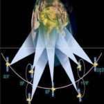
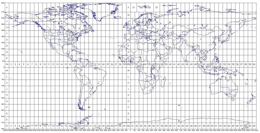
Latitude and Longitude
Latitude and Longitude is a spherical coordinate system that are not associated with a map projection. The Latitude and Longitude express locations in the terms of a spheroid, not a plane. Therefore, an image is not usually rectified to latitude and longitude, although it is possible to convert images to latitude and longitude.
Coordinate System in GIS
A Coordinate System in GIS defines how geographic data is spatially located on the Earth’s surface. It provides a framework to reference locations in space.
Key Components of a Coordinate System:
- Datum: Mathematical model of the Earth (e.g., WGS 84, NAD 27)
- Spheroid: Defines Earth’s size and shape
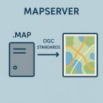
- Projection (for PCS): Method to transform 3D Earth to 2D map
- Units: Degrees (GCS) or meters/feet (PCS)
Two types of coordinate systems used in GIS:
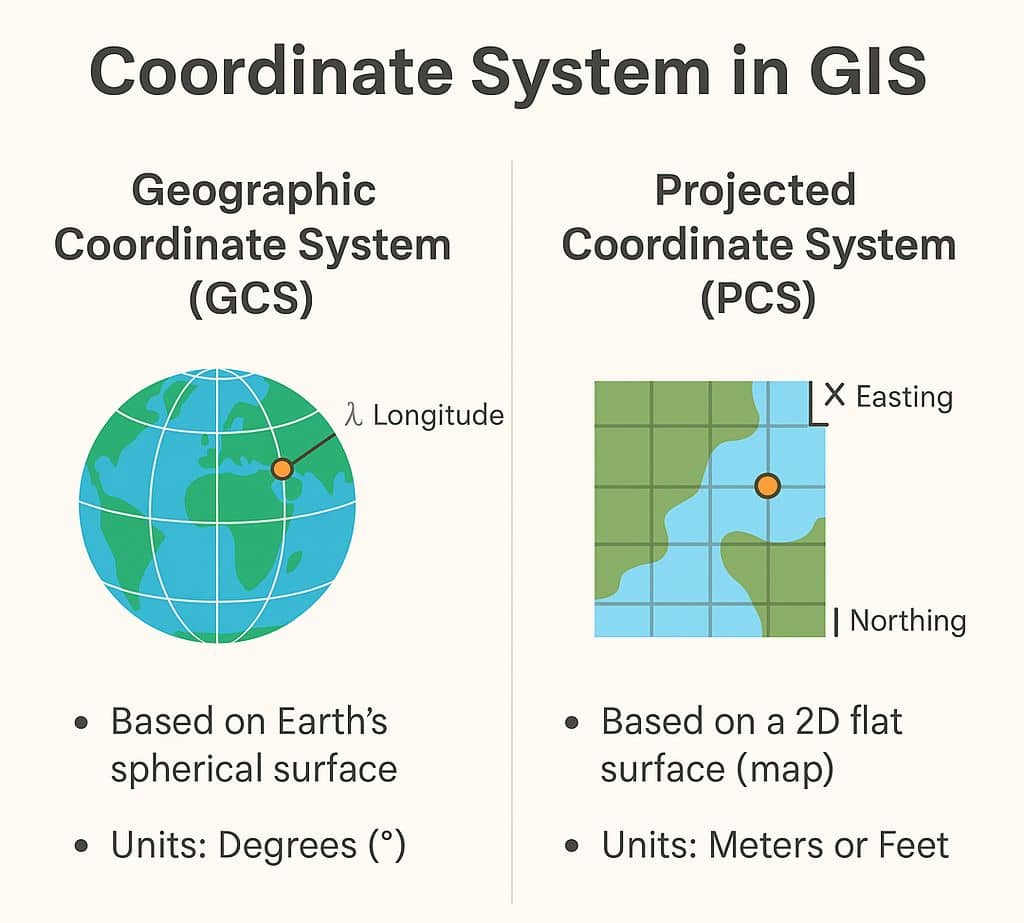
Geographic Coordinate Systems
A Geographic Coordinate System (GCS) is a reference framework that defines the locations of features on a model of the earth. It’s shaped like a globe-spherical. Its units are angular, usually degrees.
Projected Coordinate Systems
A Projected Coordinate System (PCS) is flat, it’s converts that GCS into a flat surface, using projection algorithm and other parameters. Its units are linear, most commonly in meters.
Geographic vs Projected Coordinate System
- Geographic Coordinate System defines where the data is located on the earth’s surface. Projected Coordinate System tells the data how to draw on a flat surface.
- A GCS is necessary for data to know where exactly on earth’s surface it is located. A PCS is necessary to draw the data on a flat map.
| Feature | Geographic CS (GCS) | Projected CS (PCS) |
|---|---|---|
| Shape of Earth | 3D Spherical | 2D Flat Plane |
| Coordinates | Latitude / Longitude | X, Y (Easting/Northing) |
| Units | Degrees | Meters or Feet |
| Uses | GPS, Global analysis | Local/Regional mapping |