Digitization in GIS: QGIS and ArcGIS
What is Digitization?
Digitizing or Digitization is the process of converting geographic data into a digital format, is one way to create data. There are several ways to digitize new features in Geographic Information Systems (GIS).
Digitization is a basic process in GIS that enables us to transform paper maps, and satellite images, into digital vector layers. In the digitization process, mapped features are converted into vector data by recording their coordinates as points, lines, or polygons.
These include digitizing on-screen or heads up over an image, digitizing a hard copy of a map on a digitizing board, or using automated digitization.
Digitization is extremely important in data security, space analysis, and decision-making in such areas as urban planning, environmental management, and historical research.
Types of GIS Digitization
There are four primary methods of digitizing:
- Manual Digitizing– done by digitizing tablet. This method, the operator manually traces all the lines from his hard-copy map (e.g. Toposheet) using a pointer device. It takes a lot of time, but also high accuracy.
- Heads-up Digitizing– is similar to manual digitization process, in the way the lines have to be traced by hand, but it works directly on the computer screen using the scanned raster image. Heads-up Digitizing method’s accuracy level is higher than using digitizing tablet, because the raster images are scanned at high resolution.
- Interactive Tracing method– method is an advanced technique of Heads-up Digitizing. In this process tracing one line at a time becomes faster and more accurate.
- Automatic Digitizing– is a process of converting raster to vector data is an automated method, using image processing and pattern recognition techniques. It digitizes the features using algorithm. This method is highly efficient for handling large datasets, with low time consumption.
| Digitization Type | Advantages | Disadvantages |
|---|---|---|
| Manual | High precision, suitable for complex features | Time consuming, and requires human effort |
| Automatic | Faster for large data sets, and reduces manual effort | Lower accuracy needs post- processing |
Before you can start digitizing, you must register your paper map into real-world Coordinates. This allows you to digitize features directly in geographic space. Re-registering helps ensure that your digitizing is accurate.
Types of Digitizing Errors in GIS
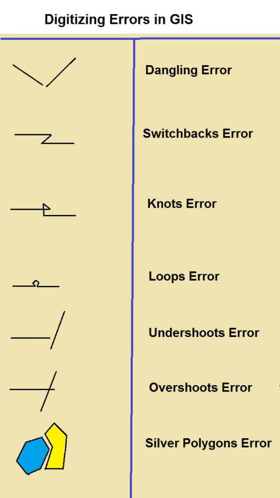
Digitizing errors can occur during the conversion process, affecting the accuracy and reliability of the digital data. There are different types of errors which can be defined as follows:
- Geodetic Errors
- Dangling Nodes
- Switchbacks, Knots & Loops
- Overshoots and Undershoots
- Silver Polygons
Digitization Process in GIS
Popular GIS Software for Digitization:
| Software | Features |
|---|---|
| QGIS | Open source supports both manual and automatic digitization |
| ArcGIS | Advanced digitizing tools support topology rules |
| Google Earth Pro | Basic digitization capabilities for mapping projects |
| AutoCAD Map 3D | Useful for engineering & cadastral digitization |
Digitizing data is an important process for a GIS. In this tutorial we will using two GIS Software to do digitization.
Step-by-Step Guide to Digitizing in QGIS
Before start Digitization, Create Shapefile (Vector Data), otherwise you can’t perform this task.
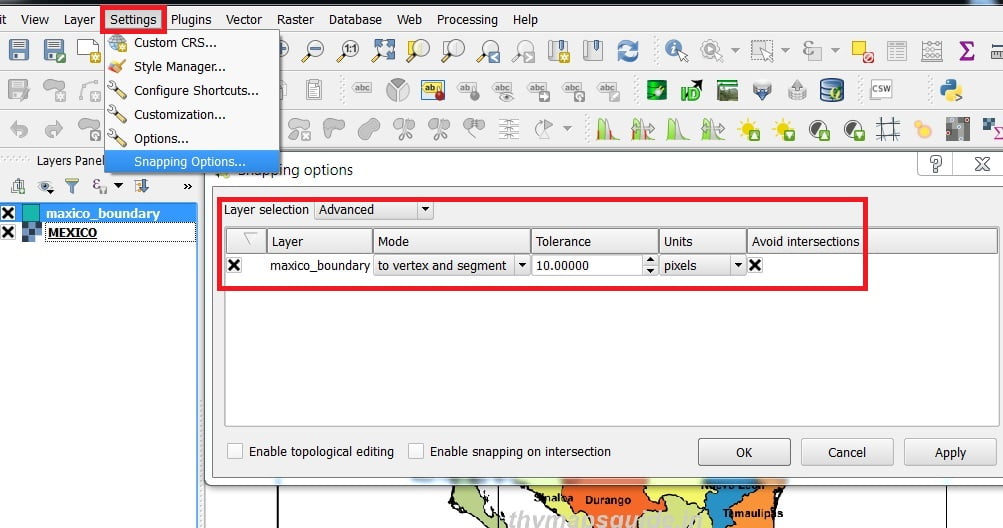
Snapping Setting:
Go to setting menu > Snapping option. In the Snapping Options window open > snapping mode– Advance > check on Layer > mode- to vertex and segment > Tolerance- 10.00000 > Unites –pixels > check on Avoid intersection.
Raster 2 Vector Conversion (screen Digitization)
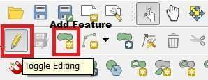
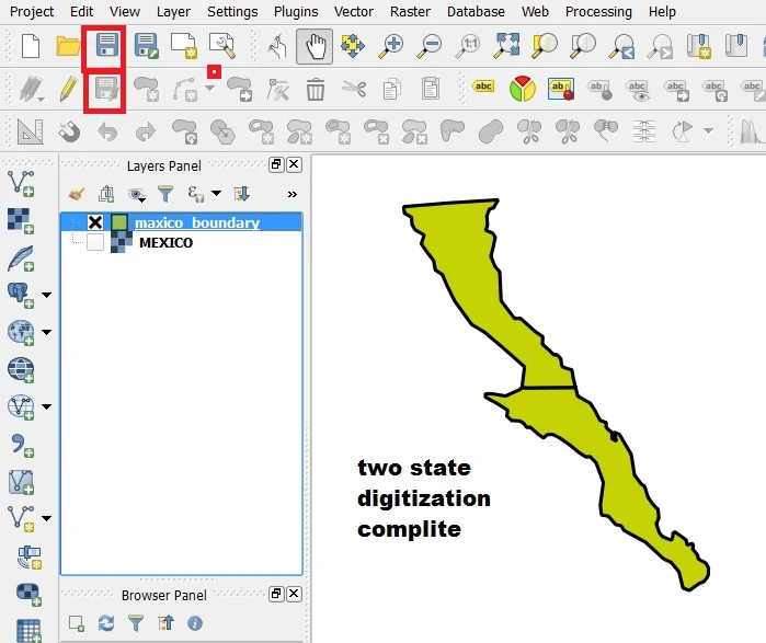
1. To start digitization (Mexico boundary), click the Toggle Editing tool. on the Digitizing toolbar.
2. click Add Feature tool on the Digitizing Toolbar and to begin digitizing right away.
You will notice that your mouse cursor has become a crosshair. This allows you to more accurately place the points you’ll be Digitizing.
3. Start digitizing by clicking on a point somewhere along the edge of the boundary.
4. Place more points by clicking further along the edge, until the shape you’re drawing completely covers the first boundary
5. To place your last point, right-click where you want it to be. This will finalize the feature and show you the Attributes. Fill in the values as below and Click OK, and you have created a new feature
6. Click Save Layer edit tool to save the feature that you digitized.
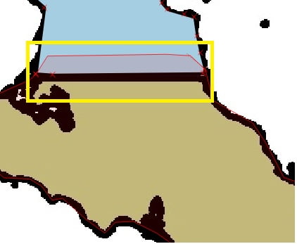
Follow the above-mentioned step and digitize another boundary. When you digitize adjacent polygons, avoid intersections function in snapping windows to help you to do it. See the right side figure that helps you to perform the digitization of adjacent polygons.
7. To place your last point, right-click where you want it to be. This will finalize the feature and show you the Attributes dialog. Input ID value and click OK button.
8. Click Save Layer Edit tool to save the feature that you digitized. Click the Toggle Editing tool to stop the edit session.
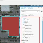
Manipulate Features using Node tool
In shapefile, the Node Tool provides manipulation capabilities of a feature similar to CAD programs. It is possible to simply select multiple vertices at once and to move, add or delete them altogether.
Start by activating the Node Tool and selecting a feature by clicking on it. Red boxes will appear at each vertex of this feature.

- Selecting vertices: You can select vertices by clicking on them one at a When a vertex is selected, its color changes to blue.
- Adding vertices: To add a vertex. simply double click near an edge and a new vertex will appear on the edge near to the cursor.
- Deleting vertices: Select the vertices and click the Delete key. To delete a complete feature use the Delete Selected tool.
- Moving vertices: Select all the vertices you want to move, click on a selected vertex or edge and drag in the direction you wish to move. All the selected vertices will move If snapping is enabled, the whole selection can jump to the reset vertex or line.
Change style and Transparency using Layer Properties
The Layer Properties dialog for a vector layer provides general settings to manage the appearance of layer features in the map (symbology, labeling, diagrams, etc.). It also provides information about the layer.
1. Double click you create a layer (Mexico boundary) in the Layers Panel or right-click > Properties, open layer properties window.
2. In Layer Properties window (see below figure), Click Style menu (i) from the left side panel, Click Simple fill option (ii). Then choose to fill color (iii) and Border color (iv) drop-down menu and select your preferred color, Border style(v) change Border width, and (vi) Set Layer transparency(vii).
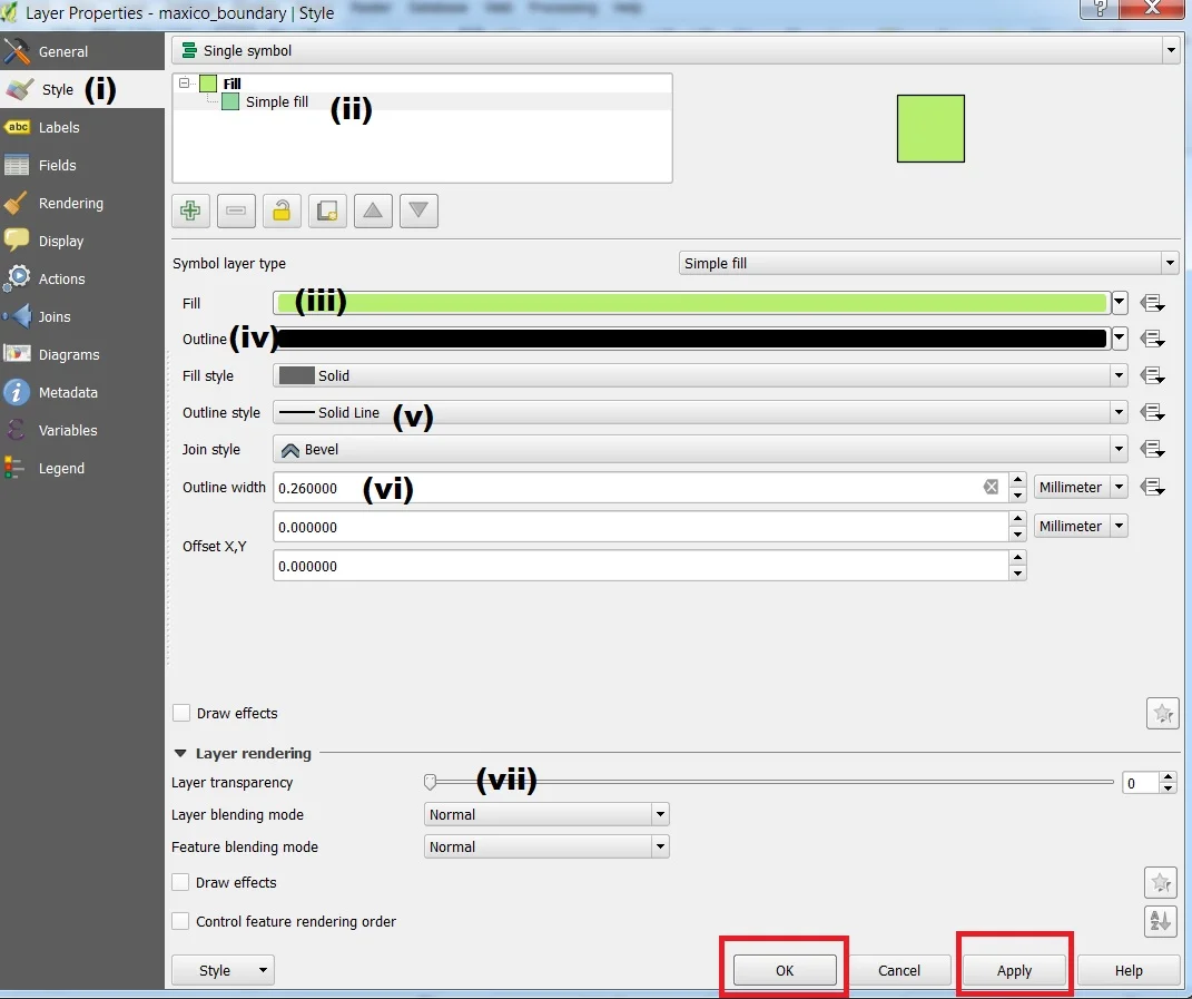
3. Click Apply and OK button to close the layer properties window.
Save Project
QGIS can save the state of your workspace into a project file using.
Project menu > Save or Save As…,and go to your folder, save the project name. Whenever you save a project in QG1S, the project file is made with the extension .qgs.
Create Line and Point Shapefile
1. Navigate to and click on the menu entry Layer> Create Layer> New Shapefile layer.
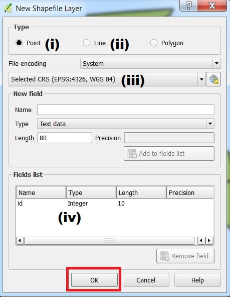
2. Choose types, what you want, Point (i), or Line (ii) > Specify the CRS WGS84 (WGS 84 is the default CRS) (iii).
By default, a new layer has only one attribute, the id field (which you should see in the Attributes list (iv) > Click OK, go your folder, require one name and save.
3. Go to setting menu > Snapping option.
In the snapping Options window open > snapping mode- Advance > check on Layer > mode- to vartex and segment > Tolerance- 10.00000 > Unites- pixels > check on avoid intersection.
Perform Road Feature Digitization
Before start digitization of Road features, if you see carefully the image then you realize that some road features are adjacent to country boundaries.
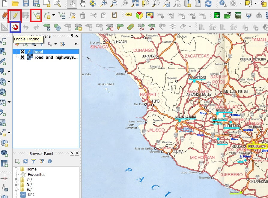
So, how shall we digitize such features? The answer is using an enable tracing option present in Advanced Digitizing Toolbar.
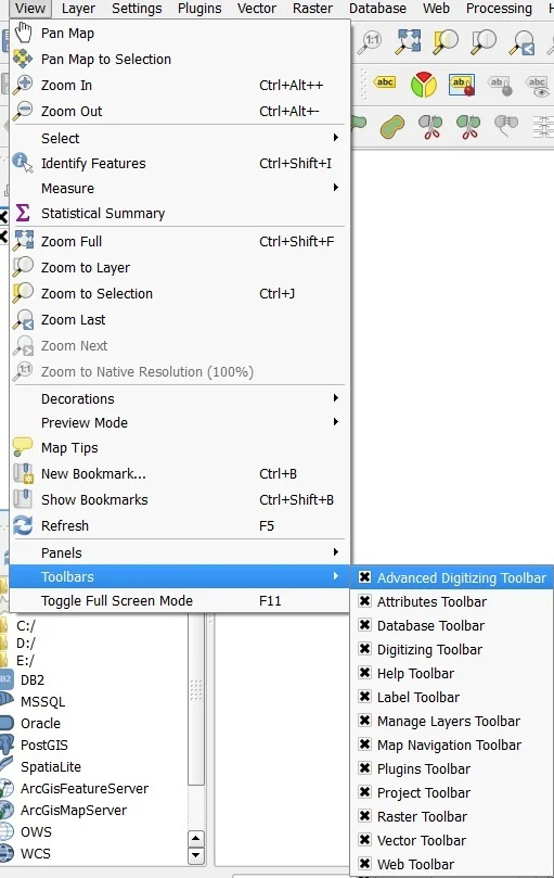
1. Click View menu – Toolbars > Advanced Digitizing Toolbar.
2. To start digitization of Road features, select the road_map layer from the Layers panel.
3. Click the Toggle Editing button on the Digitizing Toolbar > Click Enable Tracing > Click Add Feature button on the Digitizing Toolbar and to begin digitizing right away.
4. Trace boundary, digitize individual road segment, and input id.
5. Road features that are not adjacent to the boundary to be digitized in a normal way (click Enable tracing tool to make it off).
6. Click the Seve Layer Edits tool to save the feature that you digitized. Click the Toggle Editing tool, stop the edit session.
View attributes and changes feature a style of the road layer if you want in the same way mentioned earlier. Also, Save the project.
Perform Point Feature Digitization
1. To start digitization of point feature, select point layer from the Layers panel.
Click Toggle Editing button on the Digitizing Toolbar > click Add Feature button on the Digitizing Toolbar and to begin digitizing right away. Digitize all the point features and input their respective IDs.
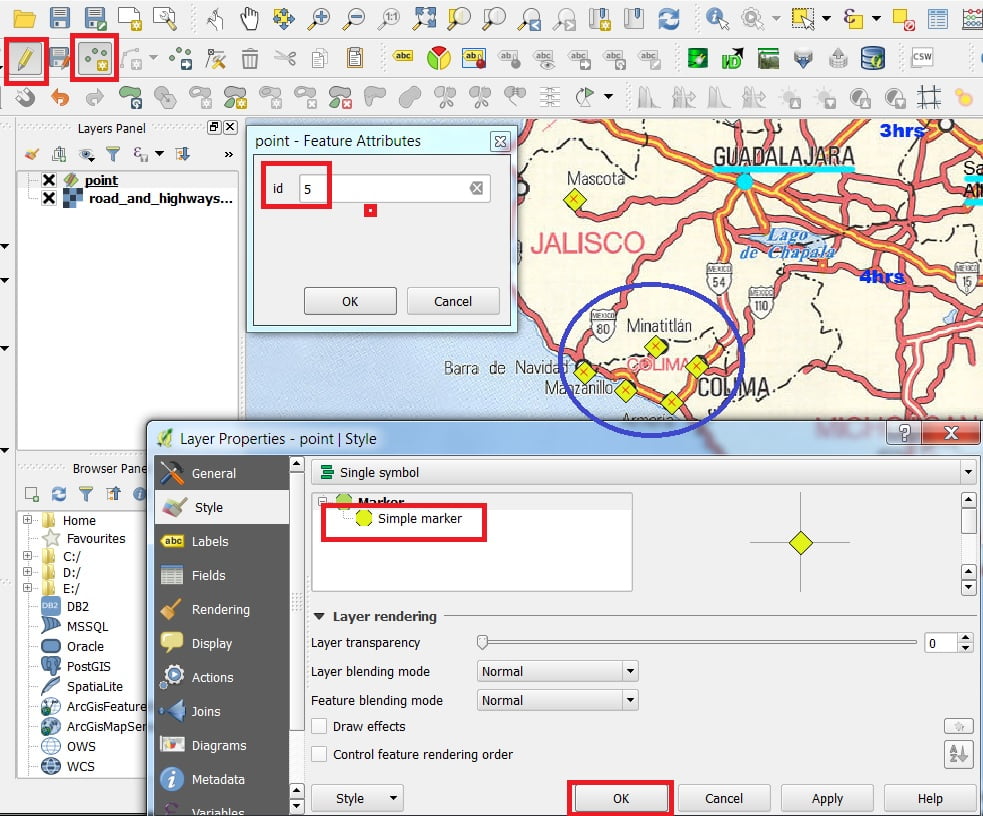
2. Click Save layer edit tool to save the feature that you digitized. Click the Toggle editing tool to stop the edit session.
Step-by-Step Guide to Digitizing in ArcGIS
Before you start digitizing, Create Shapefile (Vector Data) in ArcMap, otherwise you can’t perform this task.
Raster 2 Vector Conversion
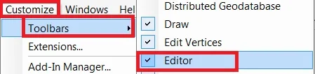
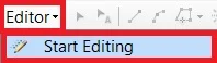
Add Editor toolbar- click Customize, select Toolbars, and click Editor.
Start an edit session by clicking Editor> Start Editing.
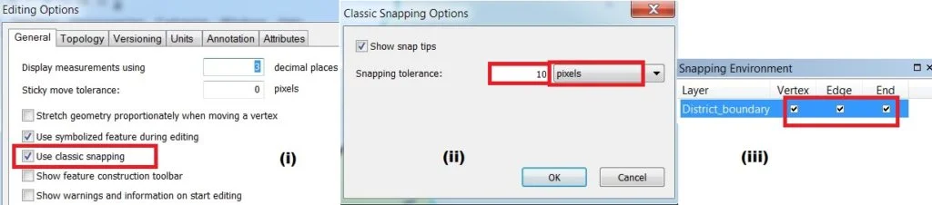
Snapping Setting:
Before Start digitizes Set-up Snapping properties 3 times.
(i) By clicking Editor> select options> Editor options window appears> click use classic snapping, then apply and ok.
(ii) Go to Editor> Snapping> Options. In the Snapping Options, the window set the snapping tolerance value 10 pixels (general between 7 to 10 pixels).
(iii)ones again dropdown Editor> Snapping> and select Snapping window. snapping environment window is open click on 3 boxes, Vertex, Edge, and End.
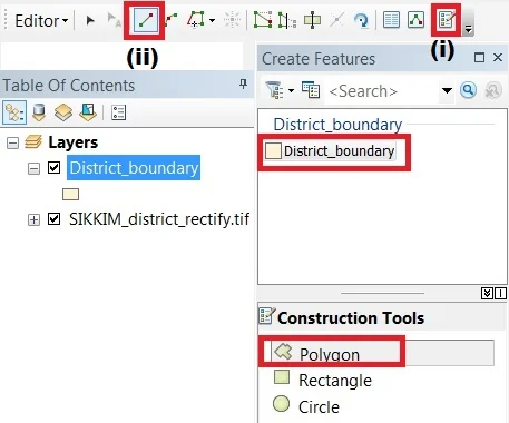
Create Feature
1. Go to Editor> select create Feature(i). Create Features window appears, choose a feature template and construction tool from the Create features Window.
2. Now select a straight segment(ii) and start Digitize.
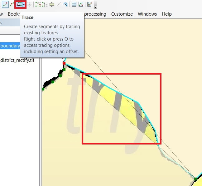
3. One Boundary Digitize is complete, now second Boundary Digitize, two Boundaries common line is joined use to Trace tool. Select Trace, click two boundaries join point, and trace it.
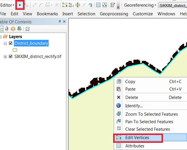
4. Anythings wrong when the digitization process, you can Edit this. Select Edit tool, click boundary line > Right click and choose Edit Vertices.
Attribute Table
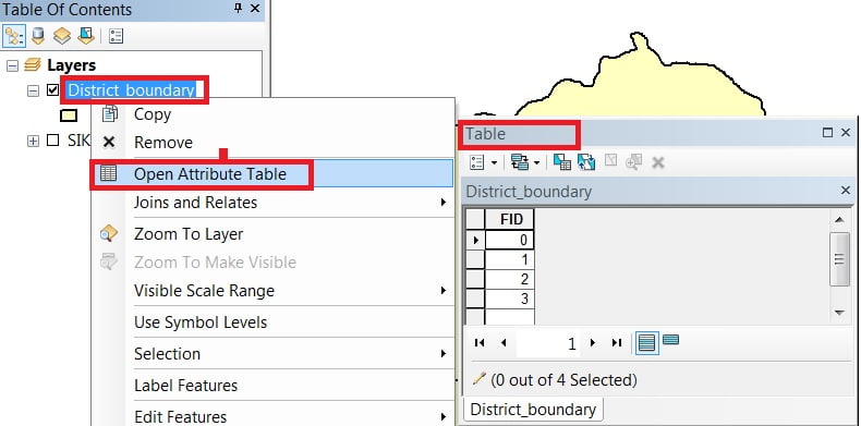
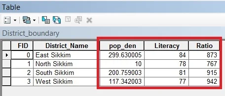
Right-click to the vector layer (District_boundary), open Attribute table. The attribute table window appears now to create a new field.
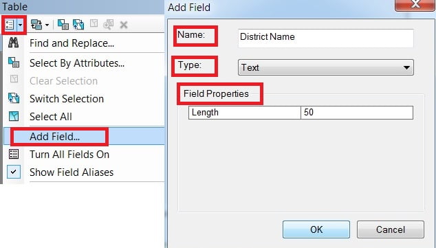
1. Add Field- Drop-down Table options and select Add field(make sure editing is off otherwise added field option is disabled).
Add field window is open fill the Name, Field Type, and Field properties then click OK.
2. Join Data- Right-click Layer> Properties > Layer properties window appears, select joins and relates. Now click the add button on the left side to join the field.
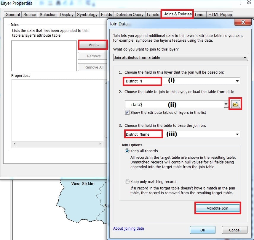
Join the Data window is open, (i) choose the field, (ii) choose the table, and (iii) choose the field to table to base the join on. Remember (i) and (ii) field is the same, otherwise it can’t be joined.
Click the validate join and then click OK.
Now check Data is joining or not. Ones again open the Attribute table and show the join Data.
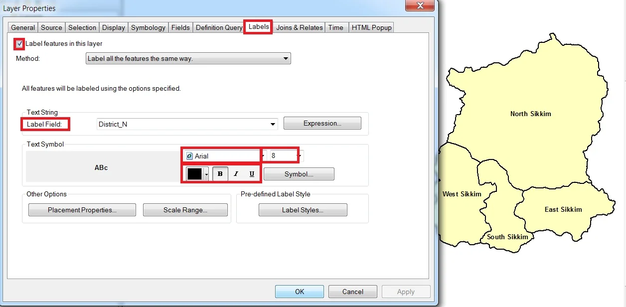
Labels
Right-click the Block Final layer in the TOC window, click Properties, or double-click the layer name to open the Layer Properties dialog box.
- Click the Labels tab.
- Click the Label features in this layer checkbox.
- In the Label Field drop-down box, choose the proper field (for example Block_No field).
- Choose a proper style for the label such as font type, size, color, etc.
Conclusion
Digitization is an important GIS process that transforms physical maps into digital forms, facilitating easier storage, analysis, and visualization. Regardless of whether it involves manual tracing or automatic raster-to-vector conversion, digitization enables GIS users to incorporate historical as well as real-time data for numerous applications.
With the progressing AI-based feature extraction and remote sensing technologies, The future of digitization is heading towards speedier, more precise, and automated processes. As GIS professionals, becoming proficient in digitization techniques, improves our skill to turn raw spatial data into meaningful insights.